My boyfriend and I went shopping for Christmas lights a couple of weeks ago. We came across a “Merry Christmas” wall sign which had LED lights attached to it and was powered through 3 AAA batteries. While it looked nice, it was annoying to operate. The only way to turn on the sign was by hitting this small switch located on its backside. That’s kinda inconvenient for something which is designed to be hung on the wall. So I decided that I could make this better by having some automatic switch to turn it off or on.
My First Idea
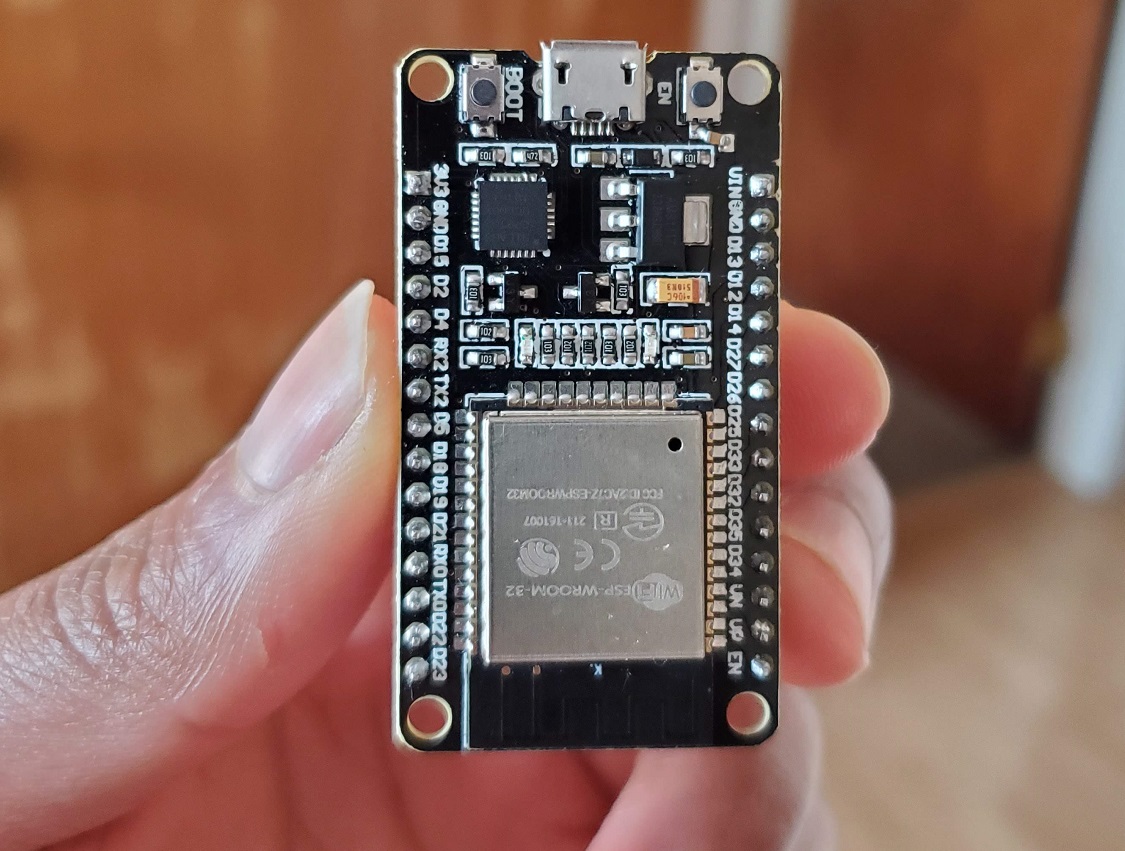
My first ideas was to hook the ESP32 up to the sign and use its WiFi capabilities to send remote commands to turn the LED lights off and on. That would’ve been great except the fact that WiFi kills a lot of energy; especially on this ESP32 Dev Board that still consumes 10mAh of power in deep sleep. Also, using the ESP32 seemed like overkill for a simple project to turn on LED lights.
Using the ATTiny85
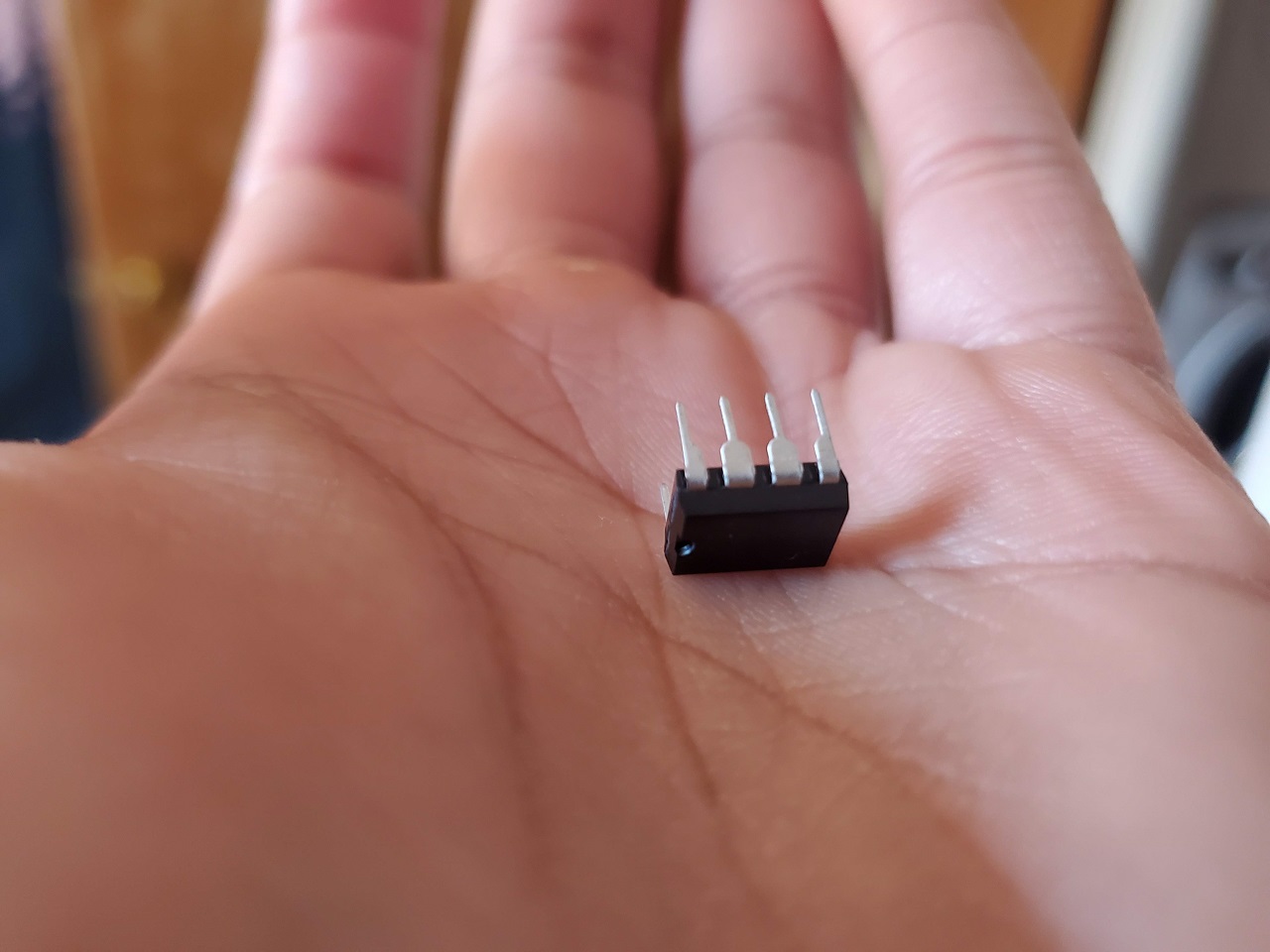
I settled on using the ATTiny85 IC. I had a couple laying around from a previous experiment I was doing months ago. They use very little energy in deep sleep mode, and are also very small. So my rough plan was to have the ATTiny85 turn on the LED lights at 5PM and turn off the LED lights at 9PM. I wanted to keep everything powered by Alkaline batteries.
What I learned
From doing this project, here’s my takeaway of random things I learned about.
LED Fairy Lights
I was confused about how the LED lights on my Christmas sign were configured. They had to be in parallel or else it would’ve took more then 4.5v (3 AAA batteries) to get them going. However, as I understood, in parallel all of these LED lights should have had a resistor connected to them. But the LED lights on my Christmas sign just had one 10 Ohm resistor connected to the battery box. After some research I learned that that was a technique that manufactures of cheap LED fairy lights use. It works cause all of the LED lights are tested to pull the exact same current (forward voltage?). As long as the power consumption of the whole string doesn’t exceed the max of all the LEDs (so it doesn’t exceed like 300mAh) then it should be fine.
RTC DS3231
I wanted my lights to come on at a certain time. Time-keeping was a completely new thing to me. I just thought that I could just tell my ATTiny85 the time and it would remember. That is not the case. Once the power goes out, so does the time. So I ended up learning about and purchasing the RTC DS3231 module . This module keeps track of the time and also provides alarm capabilities. Therefore, it could send an alarm to wake up your microcontroller at a certain time. The module also contains its own battery so if it loses its main power to VCC it will continue to keep the time in the background.
THERE IS A BUT! So here’s the thing, when the DS3231 is not connected to main power, it still should be able to wake up ATTiny85. However, after lots of research and frustration I learned that this was not possible on the module I have without making modifications to the board through soldering different parts. I said hell no to that and just accepted that I would have to keep it connected to main power. This does mean that the DS3231 will still be consuming needless energy from my battery. Also that damn power LED on it consumes nearly 2mAh by itself.
Connect all the grounds
My ATTiny85 wasn’t reading from my RTC. I checked all of the connections multiple times and confirmed everything was wired correctly. I even tried different RTC libraries and everything. After getting super desperate and posting on the Arduino forum, someone pointed out that I didn’t connect all the grounds together. So even though I had my RTC powered through a different Vcc during my testing, the grounds still needed to meetup with the same ground as my ATTiny85.
NPN Transistor
So at first, I thought I could just connect the LED fairy lights to one of the ATTiny85 GPIO pins and turn it off and on. However, with the 10 Ohm resistor that the manufacture included, it would mean that the LED lights are pulling 120 mAh (as measured through my multimeter). The ATTiny85 can handle a max of 40mAh per GPIO. Now in hindsight, I realized that I could’ve just put a larger resistor that will limit that power draw. The lights wouldn’t be as bright, but they would be safe to operate directly from the GPIO pins. I realized that a little too late and instead looked into ways that I could put the LED fairy lights on a separate power supply and just switch it off and on from the arduino.
That’s when I learned about NPN transistors. They can act like digital switches when current is applied to the base. I first got confused and ended up buying a MOSFET transitor from Microcenter though. They switch when voltage is applied to the base. However, the one I got was for really high voltage circuits. Like I would need at least 12v to turn it on. After some tinkering and frustration, I realized that a NPN transistor was what I wanted.
Even though I didn’t need to use it, I also learned how diodes are used in combination with DC motors on NPN transistors to prevent back current from happening when the motor stops. This is important because as a motor is stopping it’s generating a little back-current that could damage your circuit.
Serial Output
The ATTiny85 does not have a hardware serial. This means that you can’t just do a Serial.println like you can on other Arduino boards. Debugging without a serial would’ve been impossible. At first I thought of doing something with LED lights as an indicator. Then I learned about USB to TTL devices. I
bought one at Microcenter
and it basically allows me to connect to the RX and TX pin on my ATTiny85. Then using the
SoftwareSerial library
I can read the serial like I would on any other Arduino.
One thing is that I ended up using the <SendOnlySoftwareSerial.h> library . This allowed me to free up my RX pin. The ATTiny85 doesn’t have many PINS and I didn’t need to send commands from my PC to the Arduino. Therefore, regaining a PIN was extremely helpful.
PIN Change Interrupts
This was one of the interesting software things which I learned. So like I mentioned before, I wanted my DS3231 to trigger an alarm which wakes up my ATTiny85. This could be done through the interrupt PIN on my board (INT0). However, that PIN was already being used for one of the DS3231 connections. Looking at the PIN diagram for the tiny, I saw that all of the pins could be used as a PIN Change interrupt. Essentially, that means that any PIN could be used to wake up the ATTiny85. However, it will take a little longer because the interrupt service rountine (ISR) has to figure out which PIN actually woke it up.
Also, to configure PIN change interrupts requires you to use the native C code and not the arduino code. I mean, I guess it might be able to be done using Arduino code, but all the examples I saw used the native C code. Here’s how to enable PIN change interrupt on PIN 4.
pinMode(4, INPUT_PULLUP); //arduino code for enabling internal pull-up resistor
GIMSK |= _BV(PCIE);    // turns on pin change interrupts
PCMSK |= _BV(PCINT4);    // turn on interrupts on pins B4
sei(); // Enable interrupts
Also, the SoftwareSerial library has its own ISR that might interfere with any ISR you define in your pogrom, FYI.
The Final Result
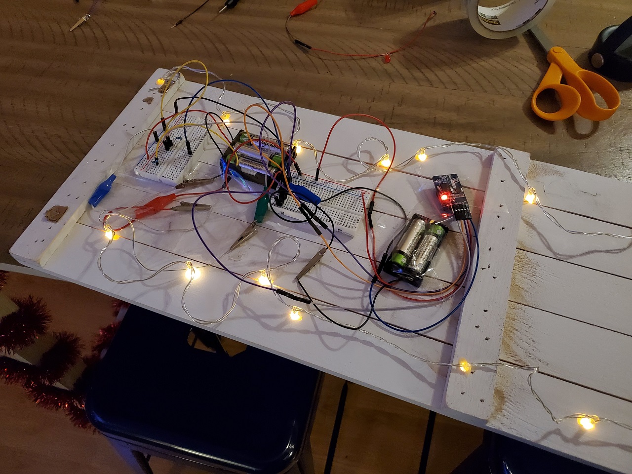
So this is the final result.
It’s not pretty. But it works! I decided to keep everything on the breadboard because I plan to take it all apart in two weeks after Christmas and I was not ready to get into soldering just yet. But it currently does what I want: Turn on the LED lights at 5PM and turn them off at 9PM. And it’s only using 1.8 mAh of power in deep sleep mode (mostly from the RTC module remaining on). That will last me the next two weeks until Christmas.
The Code
I published the code on GitHub . You can also view the code for my sketch below.
#include <SendOnlySoftwareSerial.h>
#include "RTClib.h"
#include <avr/sleep.h>
#include <avr/interrupt.h>
#include <avr/power.h>
RTC_DS3231 rtc;

int LED_PIN = 1;
int SECONDS_DELAY = 61;

SendOnlySoftwareSerial mySerial(3);  // rx, tx


void setup ()
{
   mySerial.begin(9600);
   mySerial.println("Starting up...");


   pinMode(LED_PIN, OUTPUT);

   if (! rtc.begin())
   {
      mySerial.println("Couldn't find RTC");
      mySerial.flush();
      abort();
   }
   if (rtc.lostPower())
   {
      mySerial.println("RTC lost power, let's set the time!");
      rtc.adjust(DateTime(F(__DATE__), F(__TIME__)));
   }
   //we don't need the 32K Pin, so disable it
    rtc.disable32K();


     pinMode(4, INPUT_PULLUP);


        // stop oscillating signals at SQW Pin
    // otherwise setAlarm1 will fail
     rtc.writeSqwPinMode(DS3231_OFF);

     // turn off alarm 2 (in case it isn't off already)
    // again, this isn't done at reboot, so a previously set alarm could easily go overlooked
      rtc.clearAlarm(1);
     rtc.clearAlarm(2);
     rtc.disableAlarm(2);


}


void setAlarm(const DateTime& dt){


    if(!rtc.setAlarm1(
            dt,
            DS3231_A1_Date // this mode triggers the alarm when the seconds match. See Doxygen for other options
    )) {
        mySerial.println("Error, alarm wasn't set!");
    }else {
        mySerial.println("Alarm set");
    }

}


void printDateTime(DateTime d){
mySerial.println(d.year());
mySerial.println(d.month());
mySerial.println(d.day());
mySerial.println(d.hour());
mySerial.println(d.minute());
mySerial.println(d.second());
mySerial.println("---------------------------");
}


void enterSleep (void)
{
  mySerial.println("Going to Sleep");
   GIMSK |= _BV(PCIE);    // turns on pin change interrupts
  PCMSK |= _BV(PCINT4);    // turn on interrupts on pins B4
  ADCSRA &= ~_BV(ADEN);                              // ADC off
  set_sleep_mode(SLEEP_MODE_PWR_DOWN);
  sleep_enable(); // Sets the Sleep Enable bit in the MCUCR Register (SE BIT)
   sei(); // Enable interrupts
  sleep_cpu();
   cli();                                  // Disable interrupts
  sleep_disable();
  sei();
   mySerial.println("Resuming process");
}

void loop ()
{

   DateTime currentTime = rtc.now();
  DateTime futureOnTime = DateTime(currentTime.year(),currentTime.month(),currentTime.day(),17,0,0);


  DateTime futureOffTime = DateTime(currentTime.year(),currentTime.month(),currentTime.day(),21,0,0);

  if (currentTime < futureOnTime){
     digitalWrite(LED_PIN, LOW);
    setAlarm(futureOnTime + TimeSpan(SECONDS_DELAY));
    mySerial.println("Not ready to turn on. Turning on at:");
    printDateTime(futureOnTime + TimeSpan(SECONDS_DELAY));
    enterSleep();
  }

  else if (currentTime >= futureOnTime && currentTime < futureOffTime){
       digitalWrite(LED_PIN, HIGH);
       setAlarm(futureOffTime + TimeSpan(SECONDS_DELAY));
       mySerial.println("Lights on, turrning off at:");
       printDateTime(futureOffTime + TimeSpan(SECONDS_DELAY));
       enterSleep();
  } else{
    digitalWrite(LED_PIN, LOW);
    setAlarm(futureOnTime + TimeSpan(1,0,0,SECONDS_DELAY));
    mySerial.println("Out of time range. Setting for Tomorrow");
    printDateTime(futureOnTime + TimeSpan(1,0,0,SECONDS_DELAY));
    enterSleep();
  }

   if(rtc.alarmFired(1)) {
    mySerial.println("alarm 1 has been triggered");
     rtc.clearAlarm(1);
  }

   if(rtc.alarmFired(2)) {
    mySerial.println("alarm 1 has been triggered");
     rtc.clearAlarm(1);
  }

}


ISR(PCINT0_vect){

}


